
Cadillac Escalade 2015 : B0413, B0423 DTC Temperature Control
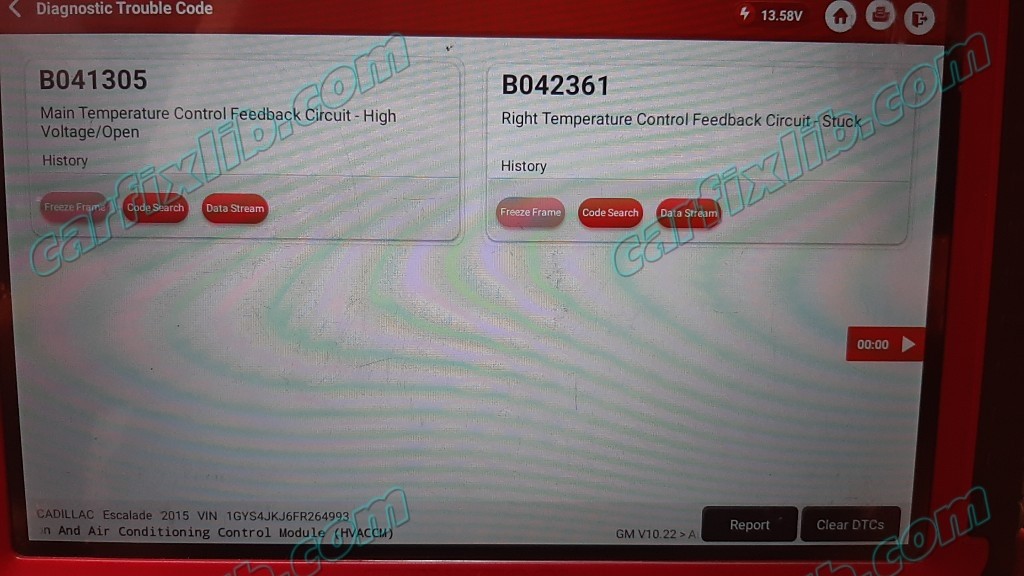
- B0413, B041305 Main Temperature Control Feedback Circuit : The HVAC control module detects the sensor signal out of range. The signal voltage is greater than 4.9 V for more than 50 ms.
- B0423, B042361 Right Temperature Control Feedback Circuit : The HVAC control module has commanded the actuator to move, and the sensor signal is not changing or has not moved to the commanded position.
Circuit/System Description
Doors in the HVAC case assembly are used to control air flow. The HVAC control module operates the doors through the use of actuators, with one actuator being used for each door. The system has the following air control doors and associated actuators: mode, left and right temperature, and recirculation. When equipped with auxiliary HVAC controls (CJ4) 2 additional actuators are added for auxiliary (rear) mode and temperature.
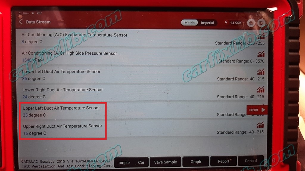
Each actuator used in the system is a 5-wire bi-directional electric motor that incorporate a feedback potentiometer. The five circuits are, low reference, 5 V reference, actuator position signal, and two control circuits. The control circuits use either a ground or 12 V value to coordinate the actuator movement. In order to move the actuator, the HVAC control module grounds one of the control circuits while providing the other with 12 V. The HVAC control module reverses the polarity of the control circuits to move the actuator in the opposite direction.
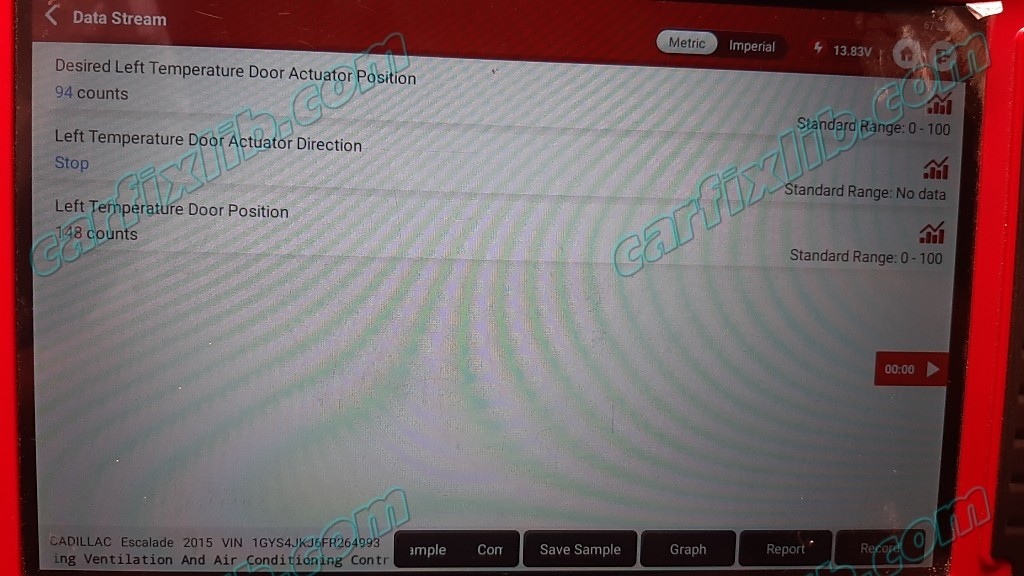
When the actuator shaft rotates, the potentiometer’s sliding contact changes the door position signal between 0–5 V. The HVAC control module converts the voltage signal to counts. The total range of the counts is 0–1024, with an operating range between 20–1000. The actual operating range of an actuator is determined during calibration. During calibration, the actuator is moved though its full range of travel and the module stores the minimum and maximum value.
Based on the desired system operation, the module sets a commanded, or targeted, value for the actuators. The control circuits are operated to move the door to the required position, and the changing position signal is sent to the module. Once the actual position signal and the commanded value are the same, the module ceases operating the control circuits and the actuator (and door) remain in the desired position.
During diagnosis, it is important to verify that the air control door and any associated components (linkage, cams, gears, etc.) operate properly. Inspect for any conditions that may limit or prevent the air control door from moving smoothly or moving through its full range of travel. Any mechanical issues should be corrected first, before proceeding with electrical diagnosis.
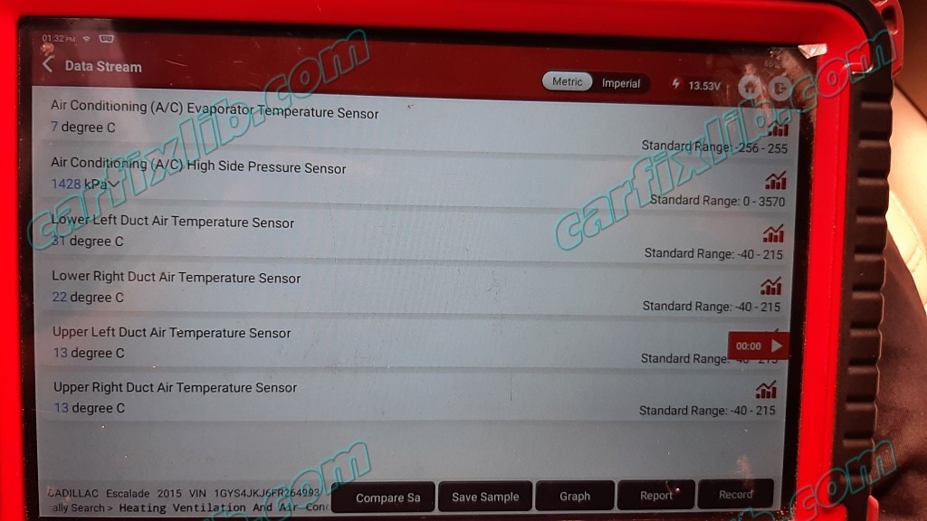
DTC B0223, B0228, B0233, B0408, B0413, B0418, B0423, B0428, B0433, B3531, B374A, or B3782
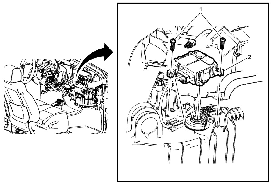
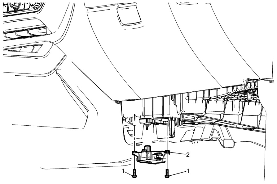
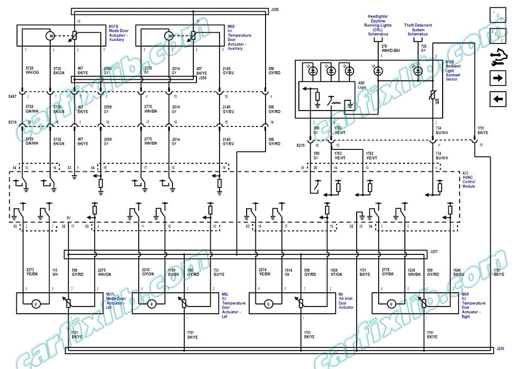
- Ignition OFF and all vehicle systems OFF, disconnect the harness connector at the appropriate door actuator. It may take up to 10 min for all vehicle systems to power down.
- Test for less than 10 Ω between the appropriate low reference circuit terminal and ground:
- M37 Mode Door Actuator terminal 1
- M46 Air Recirculation Door Actuator terminal 1
- M6L Air Temperature Door Actuator — Left terminal 1
- M6R Air Temperature Door Actuator — Right terminal 1
- M37B Mode Door Actuator — Auxiliary terminal 4
- M6B Air Temperature Door Actuator — Auxiliary terminal 4
- If 10 Ω or greater
- Ignition OFF, disconnect the harness connectors at the K33 HVAC Control Module.
- Test for less than 2 Ω in the low reference circuit end to end.
- If 2 Ω or greater, repair the open/high resistance in the circuit.
- If less than 2 Ω, replace the K33 HVAC Control Module.
- If less than 10 Ω continue => :
- If 10 Ω or greater
- Ignition ON.
- Test for 4.8–5.2 V between the appropriate 5 V reference circuit terminal listed below and ground:
- M37 Mode Door Actuator terminal 3
- M46 Air Recirculation Door Actuator terminal 3
- M6L Air Temperature Door Actuator — Left terminal 3
- M6R Air Temperature Door Actuator — Right terminal 3
- M37B Mode Door Actuator — Auxiliary terminal 6
- M6B Air Temperature Door Actuator — Auxiliary terminal 6
- If less than 4.8 V
- Ignition OFF, disconnect the harness connectors at the K33 HVAC Control Module.
- Test for infinite resistance between the 5 V reference circuit and ground.
- If less than infinite resistance, repair the short to ground on the circuit.
- If infinite resistance =>
- Test for less than 2 Ω in the 5 V reference circuit end to end.
- If 2 Ω or greater, repair the open/high resistance in the circuit.
- If less than 2 Ω, replace the K33 HVAC Control Module.
- If greater than 5.2 V
- Ignition OFF, disconnect the harness connectors at the K33 HVAC Control Module, ignition ON.
- Test for less than 1 V between the 5 V reference circuit and ground.
- If 1 V or greater, repair the short to voltage on the circuit.
- If less than 1 V, replace the K33 HVAC Control Module.
- If between 4.8–5.2 V =>
- If less than 4.8 V
- Test for 4.8–5.2 V between the appropriate signal circuit terminal listed below and ground:
- M37 Mode Door Actuator terminal 2
- M46 Air Recirculation Door Actuator terminal 2
- M6L Air Temperature Door Actuator — Left terminal 2
- M6R Air Temperature Door Actuator — Right terminal 2
- M37B Mode Door Actuator — Auxiliary terminal 5
- M6B Air Temperature Door Actuator — Auxiliary terminal 5
- If less than 4.8 V
- Ignition OFF, disconnect the harness connectors at the K33 HVAC Control Module.
- Test for infinite resistance between the signal circuit and ground.
- If less than infinite resistance, repair the short to ground on the circuit.
- If infinite resistance =>
- Test for less than 2 Ω in the signal circuit end to end.
- If 2 Ω or greater, repair the open/high resistance in the circuit.
- If less than 2 Ω, replace the K33 HVAC Control Module.
- If greater than 5.2 V
- Ignition OFF, disconnect the harness connectors at the K33 HVAC Control Module, ignition ON.
- Test for less than 1 V between the signal circuit and ground.
- If 1 V or greater, repair the short to voltage on the circuit.
- If less than 1 V, replace the K33 HVAC Control Module.
- If between 4.8–5.2 V =>
- If less than 4.8 V
- Ignition OFF, disconnect the harness connectors at the K33 HVAC Control Module, ignition ON.
- Test for less than 1 V between the appropriate control circuit terminals listed below and ground:
- M37 Mode Door Actuator terminals 5 and 6
- M46 Air Recirculation Door Actuator terminals 5 and 6
- M6L Air Temperature Door Actuator — Left terminals 5 and 6
- M6R Air Temperature Door Actuator — Right terminals 5 and 6
- M37B Mode Door Actuator — Auxiliary terminals 1 and 2
- M6B Air Temperature Door Actuator — Auxiliary terminals 1 and 2
- If 1 V or greater
- Repair the short to voltage on the circuit.
- If less than 1 V =>
- If 1 V or greater
- Ignition OFF.
- Test for infinite resistance between the appropriate control circuit terminals listed below and ground:
- M37 Mode Door Actuator terminals 5 and 6
- M46 Air Recirculation Door Actuator terminals 5 and 6
- M6L Air Temperature Door Actuator — Left terminals 5 and 6
- M6R Air Temperature Door Actuator — Right terminals 5 and 6
- M37B Mode Door Actuator — Auxiliary terminals 1 and 2
- M6B Air Temperature Door Actuator — Auxiliary terminals 1 and 2
- If less than infinite resistance
- Repair the short to ground on the circuit.
- If infinite resistance =>
- If less than infinite resistance
- Test for less than 2 Ω in each control circuit end to end.
- If 2 Ω or greater
- Repair the open/high resistance in the circuit.
- If less than 2 Ω
- Note: Before replacing an actuator, verify that there are no mechanical issues with the air control door and any associated components.
- If 2 Ω or greater
- Test or replace the actuator.
- Verify the DTC or symptom is corrected while operating the HVAC system under the Conditions for Running the DTC.
- If the DTC or symptom is not corrected
- Replace the K33 HVAC Control Module.
- If the DTC or symptom is corrected
- If the DTC or symptom is not corrected
- All OK.
Was this helpful?
1 / 0
