Cadillac Escalade 2015 – HVAC Description and Operation
The air temperature and the air delivery description and operation are divided into eight areas:
- HVAC Control Components
- Air Speed (Front)
- Air Speed (Rear)
- Air Delivery (Front)
- Air Delivery (Rear)
- Heating and A/C Operation
- Recirculation Operation
- Automatic Operation
- Engine Coolant
- A/C Cycle
HVAC Control Components
HVAC Control
The HVAC control contains all switches, buttons, and dials which are required to control the functions of the HVAC system and serve as interface between the operator and the HVAC control module. The selected values are passed to the HVAC control module via LIN-Bus.
HVAC Control Module
The HVAC control module is a GMLAN device that interfaces between the operator and the HVAC system to maintain and control desired air temperature and air distribution settings. The battery positive voltage circuit provides power that the HVAC control module uses for keep alive memory. If the battery positive voltage circuit loses power, all HVAC DTCs and settings will be erased from keep alive memory. The body control module (BCM), which is the vehicle mode master, provides a device ON-Signal. The HVAC control module provides blower, air delivery mode and air temperature settings.
The HVAC control module supports the following features:
| Feature | Availability |
|---|---|
| Afterblow | Available if reprogrammed by the technician |
| Purge | Yes |
| Personalization | Yes |
| Actuator Calibration | Yes |
Actuators
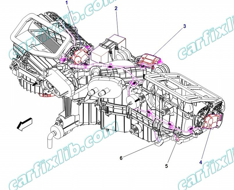
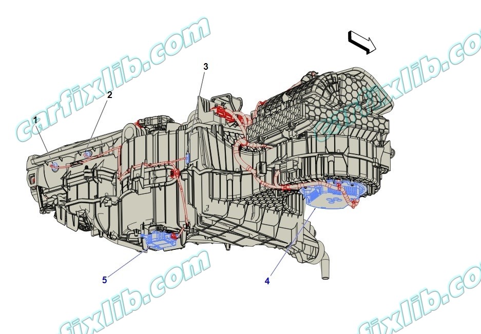
Doors in the HVAC case assembly are used to control air flow. The HVAC control module operates the doors through the use of actuators, with one actuator being used for each door. The system has the following air control doors and associated actuators: mode, left and right temperature, and recirculation.

(1) M4 Air Inlet Door Actuator
(2) K33 HVAC Control Module
(3) M6L Air Temperature Door Actuator – Left
(4) M37L Mode Door Actuator – Left
(5) B7D Air Temperature Sensor – Duct Left Lower
(6) B7E Air Temperature Sensor – Duct Right Lower

(1) B7H Air Temperature Sensor – Duct Left Upper
(2) B7J Air Temperature Sensor – Duct Right Upper
(3) B39 A/C Evaporator Temperature Sensor
(4) M8 Blower Motor
(5) M6R Air Temperature Door Actuator – Right
Each actuator used in the system is a 5-wire bi-directional electric motor that incorporate a feedback potentiometer. The five circuits are, low reference, 5 V reference, actuator position signal, and two control circuits. The control circuits use either a ground or 12 V value to coordinate the actuator movement. In order to move the actuator, the HVAC control module grounds one of the control circuits while providing the other with 12 V. The HVAC control module reverses the polarity of the control circuits to move the actuator in the opposite direction.
When the actuator shaft rotates, the potentiometer’s sliding contact changes the door position signal between 0–5 V. The HVAC control module converts the voltage signal to counts. The total range of the counts is 0–1024, with an operating range between 20–1000. The actual operating range of an actuator is determined during calibration. During calibration, the actuator is moved though its full range of travel and the module stores the minimum and maximum value. Based on the desired system operation, the module sets a commanded, or targeted, value for the actuators. The control circuits are operated to move the door to the required position, and the changing position signal is sent to the module. Once the actual position signal and the commanded value are the same, the module ceases operating the control circuits and the actuator (and door) remain in the desired position.
Blower Motor
The blower motor control module is an interface between the HVAC control module and the blower motor. The blower motor speed control from the HVAC control module, battery positive and ground circuits enable the blower motor control module to operate. The HVAC control module provides a pulse width modulation (PWM) signal to the blower motor control module in order to command the blower motor speed. The blower motor control module transfers the PWM signal into a corresponding blower motor voltage.
Duct Temperature Sensors
The air temperature sensors are 2-wire negative temperature co-efficient thermistors. The sensors operate within a temperature range of −40 to +85°C (−40 to +185°F). The sensors are installed in the air distribution ducts and measure the temperature of the air that streams from the ducts. The HVAC control module uses these values to adjust the mixed air flap position according to the requested temperature.
Evaporator Temperature Sensor
The evaporator temperature sensor is a 2-wire negative temperature co-efficient thermistor. The sensor operates within a temperature range of −40 to +85°C (−40 to +185°F). The sensor is installed at the evaporator and measures its temperature. If the temperature drops under 3°C (38°F), the compressor will be switched off in order to prevent evaporator icing.
A/C Refrigerant Pressure Sensor
The A/C refrigerant pressure sensor is a 3-wire piezoelectric pressure transducer. A 5 V reference voltage, low reference, and signal circuits enable the sensor to operate. The A/C pressure signal can be between 0.2–4.8 V. When the A/C refrigerant pressure is low, the signal value is near 0 V. When the A/C refrigerant pressure is high, the signal value is near 5 V. The engine control module (ECM) converts the voltage signal to a pressure value. When pressure is too high or too low, the ECM will not allow the A/C compressor clutch to engage.
A/C Compressor
The A/C compressor uses a conventional belt driven magnetic clutch to engage and mechanically turn the compressor. When the A/C switch is …
Air Speed
The blower control switch is part of the HVAC controls. The selected value of the blower switch position is sent to the HVAC control module via LIN-Bus. The blower motor control circuitry is integrated within the blower motor assembly. The HVAC control module provides a low side pulse width modulation (PWM) signal to the blower motor to request a specific motor speed. The blower motor translates the PWM signal and drives the motor accordingly.
Afterblow
Afterblow is a feature that dries the evaporator core by operating the blower motor after the engine is turned OFF. This reduces the amount of microbial growth that can create undesirable odors. The vehicle does not come equipped with the afterblow feature turned ON. If the afterblow feature is required due to an odor concern, it must be enabled using the scan tool Afterblow configuration function.
After the HVAC control module has been programmed for afterblow, the following conditions must be met for afterblow to operate:
- The engine has been turned OFF for at least 30 minutes.
- The ambient air temperature is at least 21°C (70°F).
- The A/C compressor operated for more than 2 minutes before shut down.
- The system voltage is at least 12 volts.
Once the above conditions have been met, the blower motor will perform the following sequence up to 5 times. This could last up to an hour:
- The blower motor will be OFF for 7–11 minutes.
- The blower motor will RUN for 25–30 seconds.
Air Delivery
The HVAC control module controls the distribution of air by the use of recirculation and mode door actuator. The modes that may be selected are:
- Defrost
- Defog
- Panel
- Floor
The desired air distribution mode can be selected with the air distribution switches at the HVAC control. The HVAC control delivers the values to the HVAC control module via LIN-Bus. The HVAC control module controls the mode door actuator so that it drives the flap to the calculated position. Depending on the position of the flap, air is distributed through various ducts leading to the outlets in the dash. Turning the mode flap to the defrost position, the HVAC control module will move the recirculation actuator to outside air, reducing window fogging. When defrost is selected, the blower motor will be activated, regardless of the coolant temperature. The HVAC control module enables a high volume of air delivered to the front defrost vents. A/C is available in all modes.
The rear window defogger does not affect the HVAC system.
Heating and A/C Operation
The purpose of the heating and A/C system is to provide heated and cooled air to the interior of the vehicle…
Engine Coolant
Engine coolant is the essential element of the heating system. The thermostat controls the normal engine operating coolant temperature. The thermostat also creates a restriction for the cooling system that promotes a positive coolant flow and helps prevent cavitation.
Coolant enters the heater core through the inlet heater hose, in a pressurized state. The heater core is located inside the HVAC control module. The ambient air drawn through the HVAC control module absorbs the heat of the coolant flowing through the heater core. Heated air is distributed to the passenger compartment, through the HVAC control module, for passenger comfort. Opening or closing the air temperature flap controls the amount of heat delivered to the passenger compartment. The coolant exits the heater core through the return heater hose and recirculates back to the engine cooling system.
A/C Cycle
Refrigerant is the key element in an air conditioning system. There are currently two approved Environmental Protection Agency refrigerants. They are R134a and R-1234yf, and either one could be used in this vehicle. R-1234yf is a newly EPA approved refrigerant, and it will require the use of an updated Air Conditioning Refrigerant Recovery/Recharge Cart/System. Refer to Refrigerant Recovery and Recharging for correct tool usage. Both refrigerants are very low temperature gases that can transfer the undesirable heat and moisture from the passenger compartment to the outside air.
The compressor builds pressure on the vapor refrigerant. Compressing the refrigerant also adds heat to the refrigerant. The refrigerant is discharged from the compressor, through the discharge hose, and forced to flow to the condenser and then through the balance of the A/C system. The A/C system is mechanically protected with the use of a high pressure relief valve. If the A/C refrigerant pressure sensor fails or if the refrigerant system becomes restricted and refrigerant pressure continued to rise, the high pressure relief will pop open and release refrigerant from the system.
Compressed refrigerant enters the condenser in a high temperature, high pressure vapor state. As the refrigerant flows through the condenser, the heat of the refrigerant is transferred to the ambient air passing through the condenser. Cooling the refrigerant causes the refrigerant to condense and change from a vapor to a liquid state.
The condenser is located in front of the radiator for maximum heat transfer. The condenser is made of aluminum tubing and aluminum cooling fins, which allows rapid heat transfer for the refrigerant. The semi-cooled liquid refrigerant exits the condenser and flows to the Receiver/Dehydrator(R/D).
The R/D contains desiccant that absorbs moisture that may be in the refrigerant system. The R/D also acts as a storage vessel to ensure that a steady flow of liquid reaches the thermal expansion valve. The refrigerant exits the R/D and flows through the liquid line to the thermal expansion valve.
The thermal expansion valve is located at the front of dash and attaches to the evaporator inlet and outlet pipes. The thermal expansion valve is the dividing point for the high and the low pressure sides of the A/C system. As the refrigerant passes through the thermal expansion valve, the pressure on the refrigerant is lowered. The thermal expansion valve also meters the amount of liquid refrigerant that can flow into the evaporator.
Refrigerant exiting the thermal expansion valve flows into the evaporator core in a low pressure, liquid state. Ambient air is drawn through the HVAC control module and passes through the evaporator core. Warm and moist air will cause the liquid refrigerant boil inside of the evaporator core. The boiling refrigerant absorbs heat from the ambient air and draws moisture onto the evaporator. The refrigerant exits the evaporator through the suction line and back to the A/C compressor, in a vapor state, and completing the A/C cycle of heat removal. At the A/C compressor, the refrigerant is compressed again and the cycle of heat removal is repeated.
The conditioned air is distributed through the HVAC control module for passenger comfort. The heat and moisture removed from the passenger compartment will also change form, or condense, and is discharged from the HVAC control module as water.
Was this helpful?
0 / 0
