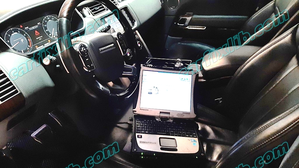
Range Rover – C1B11-62 Pressure Control Valve
Issue:
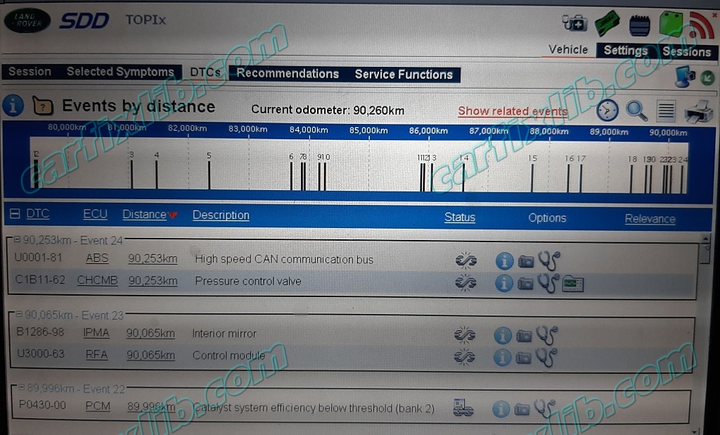
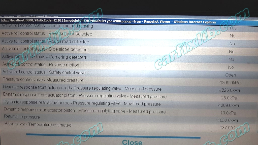
The following Diagnostic Trouble Codes (DTCs) C1119-09, C1B11-62, C1046-91, C104A-94, C104B-94, C104C-94, C1049-94 may be stored in the Dynamic Response Control Module (DRCM).
Cause:
Potential air lock in the Dynamic Response System (DRS) hydraulic circuit that can generate the above fault codes.
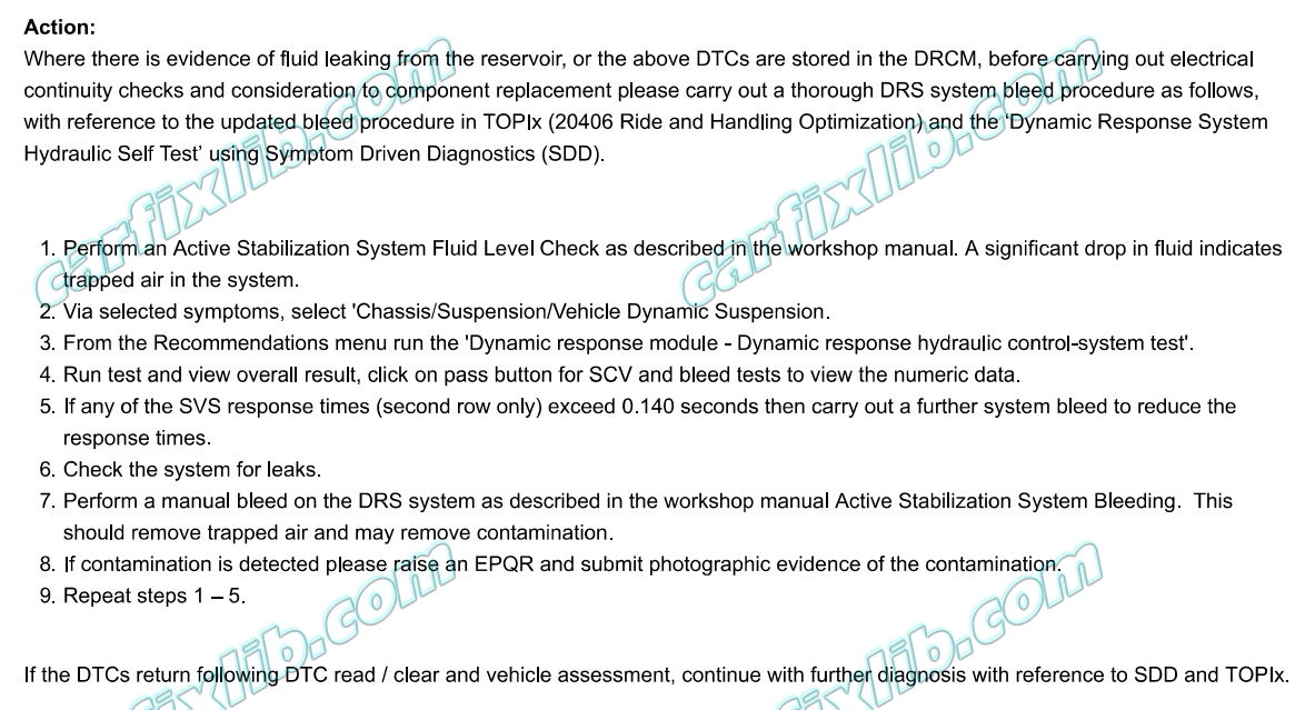
Action:
Active Stabilization System Fluid Level Check

- With the fluid temperature at normal operating temperature 50-70°C the level may be 10-15mm above this mark. Topping up at normal operating temperature should take account of this. Do not remove fluid to achieve the “MAX” level when the fluid is at normal operating temperature.
- The fluid level should be checked with engine off and engine on, any significant drop (more than 5mm) indicates trapped air in the system.
Check The System For Leaks
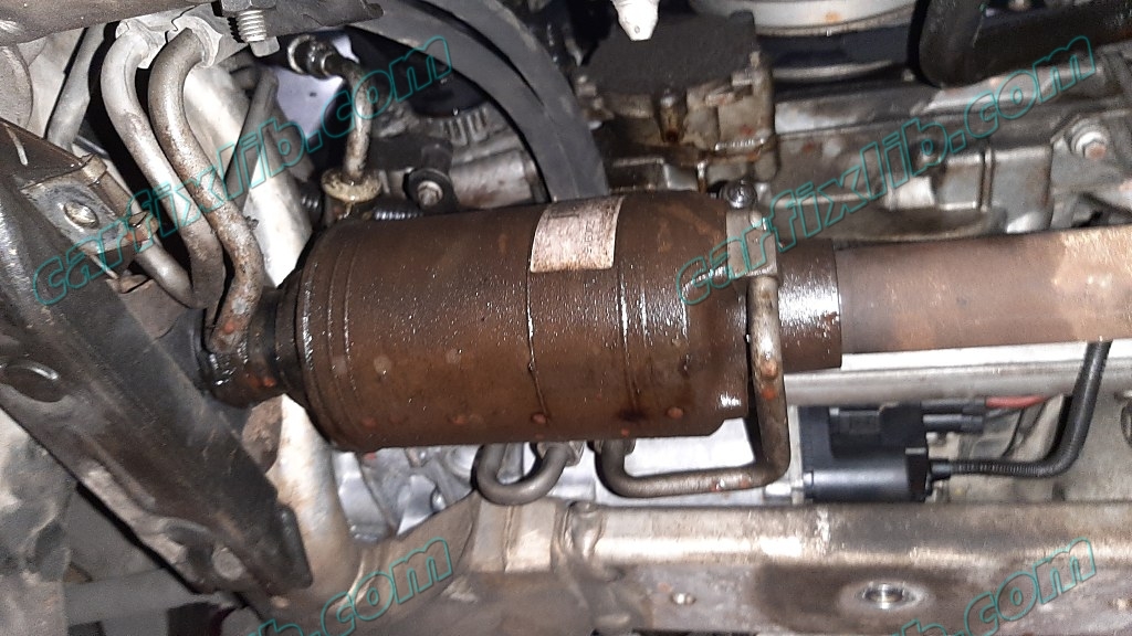
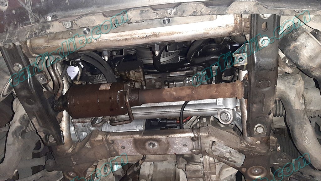
Active Stabilization System Bleeding
Special Tool

204-591-01
Dynamic Response Bleed Bottle Land Rover

JLR-204-591-03
Adaptor, Dynamic Response Bleed Bottle Land Rover
CAUTION:
Dynamic response system (DRS) components are manufactured to very precise tolerances. It is therefore essential that absolute cleanliness is observed when working with these components. Always install blanking plugs to any open orifices or lines. Failure to follow this instruction may result in foreign matter ingress to the Land Rover DRS.
NOTES:
- The first part of this procedure should be completed if the following components have been removed:
1.

Check and top-up the dynamic response system fluid reservoir. Then squeeze the suction hose (feed hose to pump from reservoir) several times to displace air that may be trapped under the fine mesh of the reservoir suction side filter.
2.

Install the new adapter to the Dynamic response bleed bottle.
3.

NOTE:
Install the special tool to the dynamic response reservoir. Section 2 to 4 is only required if the reservoir has been drained and or pump /suction hose has been changed.
- Completely fill the reservoir with fluid.
- Make sure the pressure regulator on the special tool is turned OFF.
- Fill the special tool bottle approximately three-quarters full with fluid.
- Connect the special tool to a suitable workshop air supply.
- Using the special tool pressure regulator, carefully increase the air pressure to approx. 0.3 – 0.7 Bar (5 – 10 PSI).Special Tool(s): 204-591-01 , JLR-204-591-03
4. Start engine and run for 1 minute.
5. WARNING:
The special tool is still pressurised when the source air pressure is removed. Release air pressure within special tool slowly before removing. Remove the special tool from the dynamic response system reservoir.
Steps 6 to 14 :
15. For valve block or pipe removal and replacement, open all four actuator bleed screws by half a turn.
16. CAUTION:
The dynamic response bleed tool fluid reservoir must remain full with new, clean fluid, at all times during bleeding.Bleed the dynamic response system until a flow of clean, air-free fluid is being pumped into all 4 bleed jars and close bleed screws.
17.

Remove and discard the front right side lower stabilizer bar link nut.
18.

Open the right bleed screw and stroke the right arm fully down. Allow fluid to run for a further 5 seconds. Close bleed screw.
19.

Open the left bleed screw and stroke the right arm fully up. Allow fluid to run for a further 5 seconds. Close bleed screw.
20.

Install and tighten a new front right side lower stabilizer bar link nut.Renew Part: Stabilizer bar link retaining nut(s) Quantity: 1.Torque: 185 Nm
21.

NOTE:
Right side illustration shown, left side is similar.
Remove and discard both the rear upper stabilizer link nuts.
22.

Open the right bleed screw and stroke the right arm fully down and left arm up. Allow fluid to run for a further 5 seconds. Close bleed screw.
23.

Open left bleed screw and stroke the right arm fully up and the left arm down. Allow fluid to run for a further 5 seconds. Close bleed screw.
24.

NOTE:Right side illustration shown, left is similar.Install and tighten 2 new stabilizer bar link nuts.Renew Part: Stabilizer bar link retaining nut(s) Quantity: 2.Torque: 185 Nm
25. WARNING: The special tool is still pressurized when the source air pressure is removed. Release air pressure within special tool slowly before removing. Remove the special tool from the dynamic response system reservoir.
Stop the manual bleed in approved JLR (Jaguar Land Rover) diagnostic tool and check the bleed.
26.

- The fluid level should be set to the “MAX” line with the fluid at 20°C.
- With the fluid temperature at normal operating temperature 50-70°C the level may be 10-15mm above this mark. Topping up at normal operating temperature should take account of this. Do not remove fluid to achieve the “MAX” level when the fluid is at normal operating temperature.
27. The fluid level should be checked with engine off and engine on, any significant drop (more than 5mm below MIN level) indicates trapped air in the system. If the fluid level drop is significantly greater than 5mm, a system re-bleed from step 2 will be required.
28.
- Check front bleed:
- Disconnect only one front stabilizer link. Stroke the arm up and down, free play travel should be less than ±10mm. If greater than ±10mm travel observed and/or spongy feeling, a system re-bleed will be required.
- Install and tighten a new stabilizer link nut.Renew Part: Stabilizer bar link retaining nut(s) Quantity: 1.Torque: 185 Nm
29.
- Check rear bleed:
- Disconnect only one rear stabilizer link. Stroke the arm up and down, free play travel should be less than ±10mm. If greater than ±10mm travel observed and/or spongy feeling, a system re-bleed will be required.
- Install and tighten a new stabilizer link nut.Renew Part: Stabilizer bar link retaining nut(s) Quantity: 1.Torque: 185 Nm
30. Repeat steps 14-25 if required.
31.
- Check all bleed screws are fully closed.Torque: 15 Nm
- Install the bleed screw covers.
32. Install the engine undershield. For additional information, refer to: Engine Undershield (501-02 Front End Body Panels, Removal and Installation)
33. If the valve block has been replaced run the auto bleed procedure from within the approved Jaguar Land Rover diagnostic equipment to release air that may be trapped in the block. This requires the engine to be running. Using the approved JLR (Jaguar Land Rover) diagnostic equipment clear pressure sensor adaptive data.
34. Using the approved Jaguar Land Rover diagnostic equipment complete hydraulic system response test to confirm correct system operation.
35. Drive the vehicle for approximately 15 minutes performing maneuvers which energize the system and include wheel inputs.
Was this helpful?
13 / 0
